

Concept / Technical diagram
Technical diagram
An explanatory diagram showing parts connections and functions with lines and symbols
An explanatory diagram showing parts connections and functions with lines and symbols.

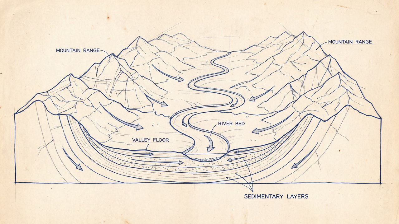
Valley with a river and mountain ranges
Both languages share the English example images. Japanese prompts are the recorded translations.
A phrase to start with
Shows parts and connections with lines and symbols.
Appearance and effects
Shows function by separating parts connections and notes.
Visual traits
- parts
- connection lines
- annotations
Expected changes
- Parts are more likely to be distinguished
- Connection lines and annotations are more likely to appear
Five examples
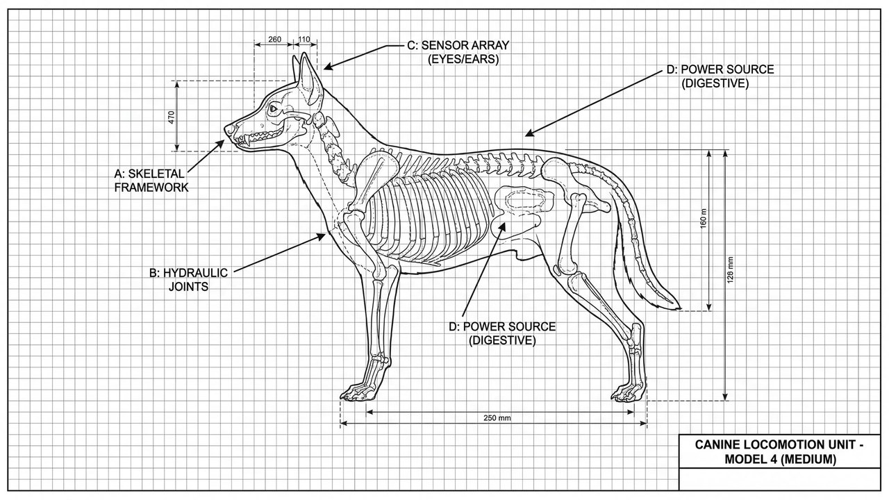
1 — Medium-sized dog
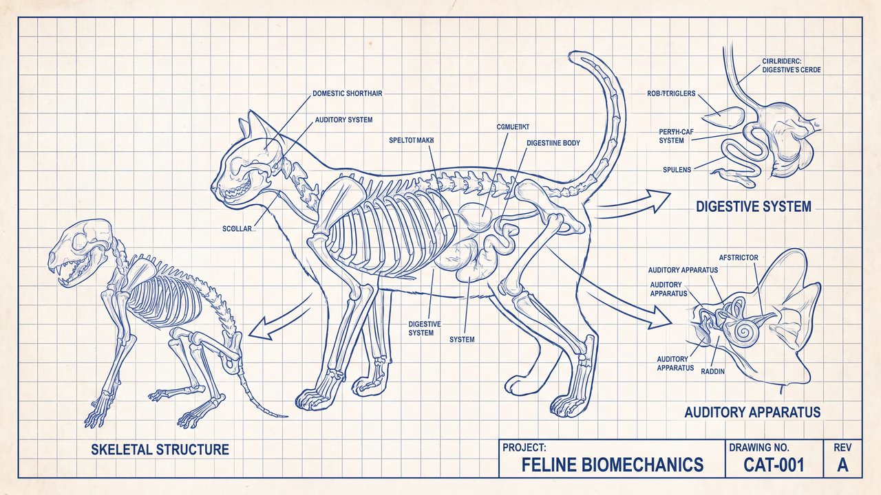
Open image ↗2 — Cat
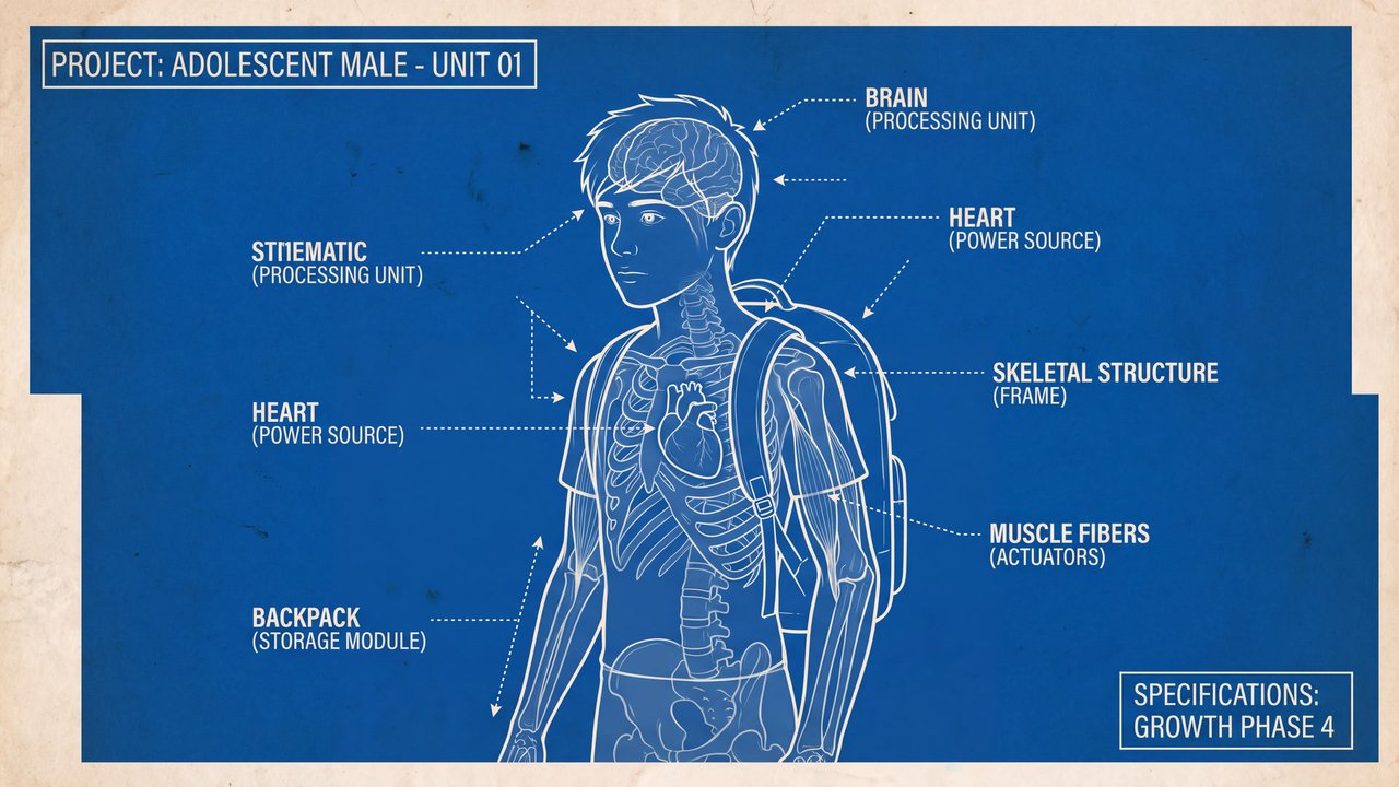
Open image ↗3 — Teenage boy
Open image ↗4 — Unoccupied interior
Open image ↗5 — Valley with a river and mountain ranges
Open image ↗Meaning and scope
Definition
An explanatory diagram showing parts connections and functions with lines and symbols. It does not guarantee design accuracy buildability or safety.
In more detail
It distinguishes parts and uses lines arrows and notes to trace connections and functions. Specifications require separate verification.
Includes
- Explanatory diagrams showing parts and connections
Excludes
- Accurate manufacturing drawings
- Safe assembly procedures
- Certified specifications
What this does not imply
- Design accuracy
- Manufacturability
- Safety assurance
Variability
Because the source is a weakly direct general reference, connection and dimension accuracy may vary.
Usage and adjustments
Usage
- Clearly separate parts and connections
- Verify specifications separately
Distinguish similar expressions
- Use verified documents for manufacturing or safety decisions
Typical uses
- Explain relationships among parts
- Show a functional overview
Possible failure modes
- Connections conflict
- Notes are illegible and can mislead
Content updated:
From the same theme
Items linked through explicit membership in the same theme.

Valley with a river and mountain ranges
Concept
Idea relationship diagram
An explanatory diagram showing elements and relationships through lines and placement.
Compare ↗
Valley with a river and mountain ranges
Concept
Comic panel
A framed area that separates one unit of content.
Compare ↗